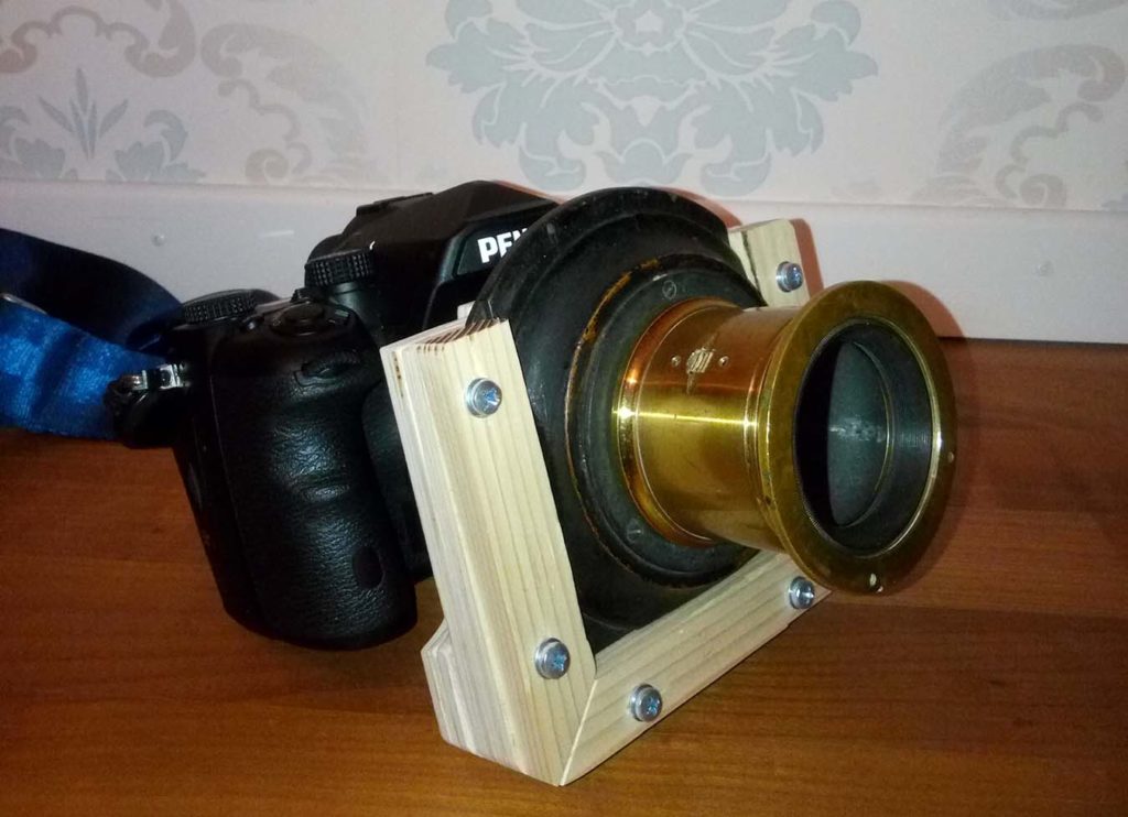
Hello everyone,
As promised, here’s a step by step to how I built my Petzval’s adapter. This will be a very image heavy post and I apologize in advance if I don’t quite nail the formatting…
In my last post I left you with the lens disassembled. I did this for two reasons.
1) to verify that it is an actual Petzval design and that the elements are all assembled in their correct orientation. Note: be careful taking apart a lens of this age, I have read about cases where the glass cracked during reassembly. We don’t want that.
2) to clean and polish it a bit.
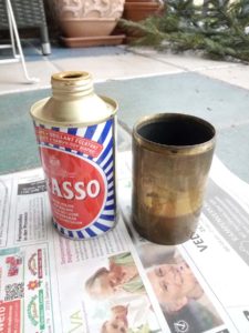
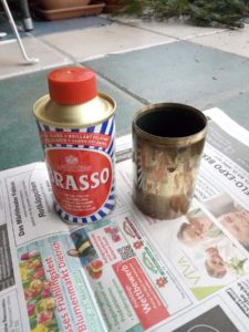
I do admit, I was a bit skeptical about how that rough polish turned out, but I very soon noticed that it suited it quite well.
Next I disassembled a Cosinon 135/2.8 I got for free a while back and was in a really bad condition to salvage it’s m42 mount.
Here I’m in the planning stage. If there ever was any more planning than a vague idea!
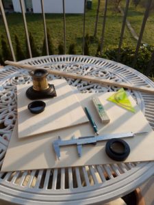
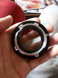
Right here I’d like to mention that I measured the Flange Focal Distance by holding the lens to a wall and measuring how far away I had to move it in order to receive a sharp image on said wall. With that I calculated how many sheets of plywood I’d roughly need.
Anyways, I’ll let a few pictures speak at this point.
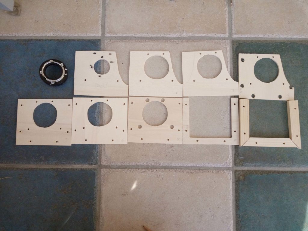
What I did not take photos of is me cutting the ‘screws’ to hold the whole thing together.
I used a threaded rod and cut it to size with the help of a dremel and used a nut on either side to create sort of a bolt.
The front ‘frame’ part, into which the lensboard slides, is attached with six of these bolts, which drive through the first four layers of the adapter and the rear part is attached by means of four bolts, creating an overlap of two (three in my newest revision) plywood boards.
I decided to build the adapter in two parts in case I need to adjust something or would like to create a tilt/shift adapter without needing to build the whole thing again and the above way seemed the safest solution.
The cut-outs on the pieces in the top row are to accommodate my fingers when holding the camera. I initially tried without them but quickly noticed that it was impossible to hold the grip without a cut-out!
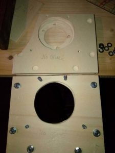
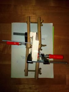
And finally, the two parts screwed together, combined and mounted to the K-1!
If you look closely you’ll notice a few things that aren’t quite correct yet, namely the orientation of the rack & pinion focus and the lack of the pinion.
One of the “original” screws wasn’t the correct one and I spent a considerable amount of time looking at possible screw threads used towards the end of the 19th century. You wouldn’t think so, but it’s actually quite an interesting topic!
Part three will follow in the next few days.
Thanks for reading & stay tuned!
Geoffrey


